(August 2022)
I first heard about TP4056 from various Youtubers - many years ago.
Modules equipped with that chip are dirt-cheap; yet allow for easy and safe charging of the LiPos in our designs.
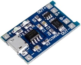
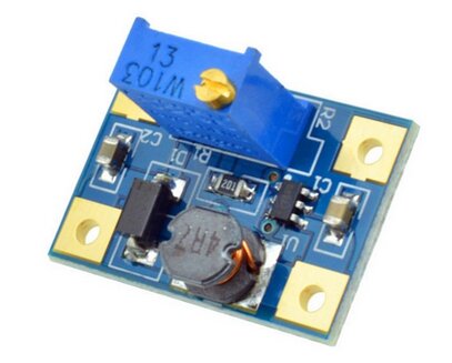
TP4056 module
I proceeded to use these modules in my experiments. The setup was easy: the LiPo gets connected to B+ and B-, and my load was powered from OUT+ and OUT-.
Whenever I wanted to charge my LiPo, I'd plug my USB powerbank to the TP4056 module input - and everything worked fine; the LiPo charged at the max current I wanted (selected via a configuration resistor on the module board).
But sometimes, I wanted to charge the LiPo and feed my load. At the same time.
This is apparently called "Load Sharing", since the power provided at the input is shared by both your load, and your LiPo charging.
Following the example of the "expert" Youtubers, I did the same thing in this scenario as well: I'd plug my powerbank in the TP4056 module, and let it charge the LiPo, and simultaneously, power my circuit from the OUT+ and OUT- points.
What I did not know, was that this was stupid - and dangerous.
Why?
Zak's article, linked above, refers to a design that uses an MCP73831; but what he says applies identically to the TP4056 as well; and in fact, to any charging circuit.
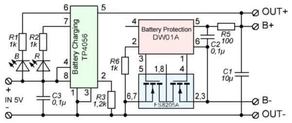
TP4056 schematic
Executive summary:
The charging chip tracks the battery's "full" condition by monitoring the current "going in". If in addition to charging the LiPo, you also drive your load... well, the chip is getting the wrong kind of feedback!
For example: let's say that normally, the TP4056 module will use the two MOSFETs to disconnect your battery's "B-" when the charge current falls below 10mA. If your load pulls, say, 15mA... the chip will never disconnect your battery! You will end up "trickle-charging" your LiPo forever.
Solution - a P-channel MOSFET, setup in reverse
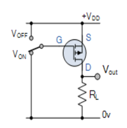
Zak's solution is shown on the schematic on the left, below. You'll notice that the MOSFET is actually connected in reverse to the usual P-channel setup (on the right) - input is to the Drain, and output is from the Source:
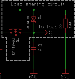
The top-green-line carries 5V from USB input to the Gate;
the middle-green-line carries OUT+ from TP4056 to the Drain
So how does this work?
When there's no USB connection, the top-green-line is pulled down with the 100K to ground. That means the voltage at the gate drops to 0V. Now think of the internal MOSFET diode as dropping the "usual" 0.7V from whatever it sees on the left (i.e. on the Drain). It follows then, that the voltage at the source drops to V(Drain)-0.7V. Given the LiPo's voltage ranges between 3V and 4.2V, this puts the source voltage to something between 2.3V and 3.5V; which is more than enough V(GS) to make the FET fully conduct. We therefore get a "direct connection" between Drain and Source, and our battery voltage goes through the FET and powers our load.
When there's a USB connection, the top-green-line is at 5V. That means the diode D1 is another (higher) source of voltage for our MOSFET's Source; even after accounting for the usual 0.3V drop of a Schottky, we drop from 5V to, say, 4.7V. The FET now sees a different story for V(GS) - it sees the drop of the Schottky! It therefore doesn't conduct, and the battery gets completely cut off. Our 4.7V go on to power our load, and at the same time, our completely isolated LiPo gets charged by the TP4056. When that charge current goes below our configured threshold, the battery's B- will be properly disconnected.
Put to use
I proceeded to modify one of my prototypes to implement this configuration on a design I did a couple of years ago, that uses a GPS/Galileo receiver, an RTC clock and a 16x2 LCD, driven and controlled by an Arduino. It works quite well, getting accurate location/time information.
And yes, as seen below, I put it all on cardboard. Fire hazard on steroids :-)
All I needed to do, was to find a place for the resistor, Schottky and the FQP27P06. Once I managed that, my multimeter showed that when I connected my TP4056 to my USB powerbank, the MOSFET's source ended up at 4.6V...

...and when the powerbank was unplugged, the Source dropped to 3.65V (as expected; that was indeed my LiPo's charge level at the time):

In plain words: it worked :-)
In this prototype, the Source of the FET is then connected to a B6288-based boost converter...
...that takes the voltage up to 5V. That is then used to feed the Arduino and all the rest - and it works regardless of whether the boost converter sees V(battery) or 4.7V as an input.
Summary
This was a very simple modification to my charging circuitry; and it allowed me to do proper load sharing. I strongly advise you to do a similar modification, if (like me) you used your TP4056 to power your load and charge at the same time. Don't do that. Also, checkout Zak's article: it has a lot more details and theory, and many interesting discussions he has with people that doubt his design.
They shouldn't - it works perfectly.


| Index | CV | Updated: Sun Nov 19 23:06:10 2023 |