(July 2019)

Remote power on/off and remote serial via ESP8266
For two reasons:
- By far the most important: because I enjoyed doing it :-)
- It allows me to fully administrate the machine remotely (BIOS settings, power, etc)
and allows me to remotely poweron/poweroff my AtomicPI
What is this about?
It's about a single-board computer (SBC) that I wanted to control remotely - my Atomic PI. I wrote about this SBC a month ago - it's an unbelievably cheap (35$) Intel-based computer, with many features. Amongst them: 2GB of RAM, 16GB of EMMC storage and a 4-core Atom CPU.
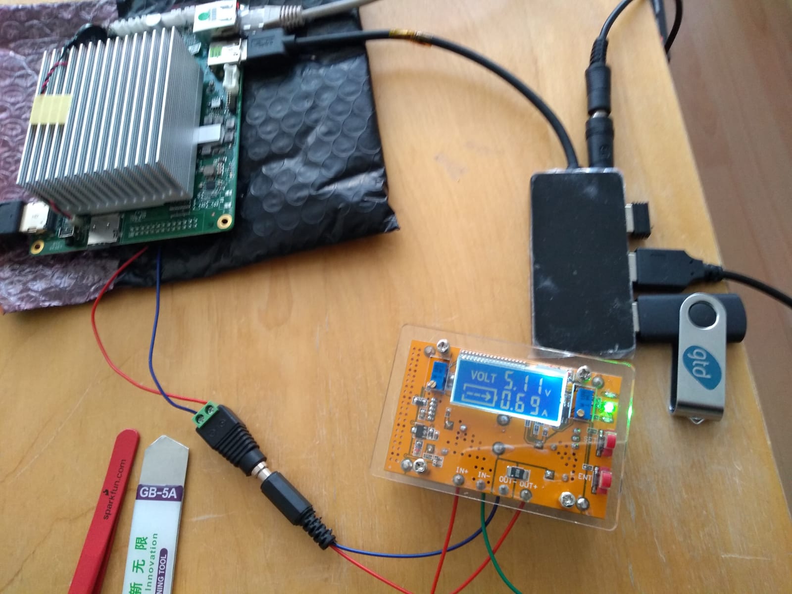
The AtomicPI needs to be powered by a good, solid 5V power supply - and since I measured its current consumption (see article for details) I knew that my Raspberry PI's power supply is more than up to the task.
So I had to splice a jack - that would allow me to plug into my custom AtomicPI power adapter.
After some cutting, kapton tape-ing, soldering and heat-shrinking...
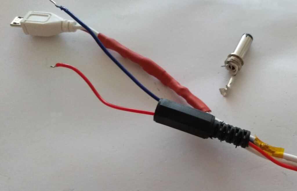
Splicing power from the Raspberry PI power supply
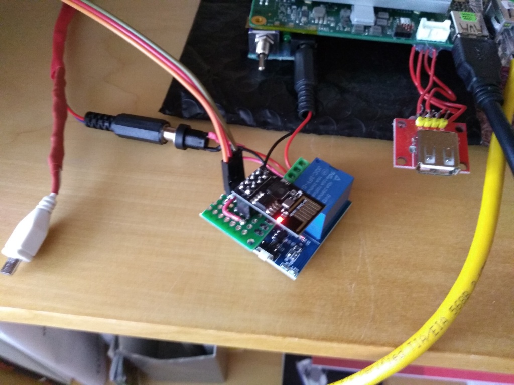
...the power supply was ready - and I could connect it to an ESP8266-based power module:
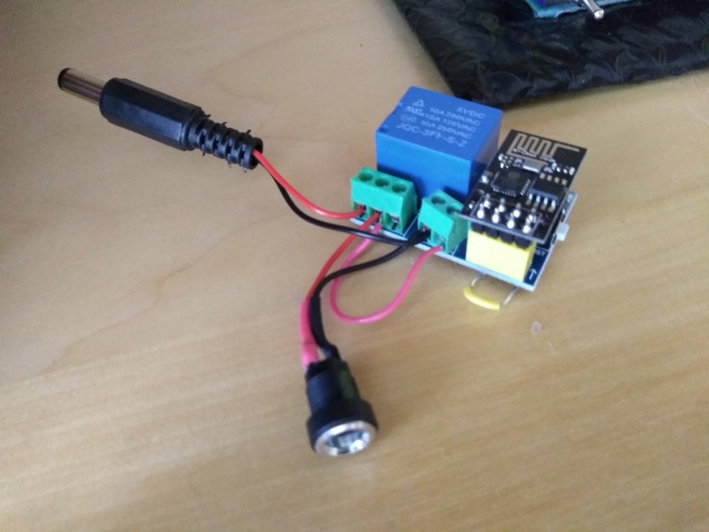
Stealing 80mA, but giving a remotely-controlled 5V supply.
The ESP8266 board (more specifically, ESP01/relay module) is a dirt-cheap one (1.8 Euros as of July 2019) that I bought from AliExpress.
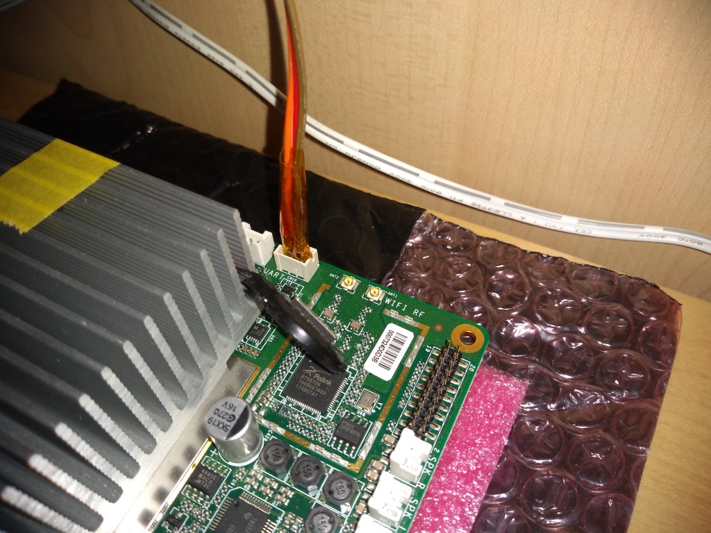
What I didn't know when I bought it, is that the PCB design had two flaws:
- The 10K Ohm R2 resistor had to be removed
- The
VCC(Pin 1) andCH_PD(Pin 3) had to be bridged (that's the small yellow wire you see protruding in the picture above).
Oh well - for that price, including shipping, I shouldn't complain too much. Diagnosing and fixing things is, after all, what makes this fun :-)
Now, all that was left was to program the ESP8266 with my own software.
What, you actually expected me to trust closed-source SW connecting to my Wi-Fi?
Are you serious? :-)
A bit of coding
There are tons of examples on the Web, demonstrating how to boot up a simple Web server on the ESP8266 - I did a very simple implementation that controls the GPIO0 pin (since that's the one that the PCB routes to the relay control):
...

const char* ssid = "Your SSID goes here";
const char* password = "Your WiFi pass goes here";

ESP8266WebServer server(80);

...

server.on("/", handleRoot);

auto redirect = []() {
    server.sendHeader("Location", String("http://") + WiFi.localIP() + String("/"), true);
    server.send(302, "text/plain", "");
};
server.on("/poweron", [&]() {
    if (!poweredUp) {
        poweredUp = true;
        digitalWrite(controlPin, 1);
    }
    redirect();
});
server.on("/poweroff", [&]() {
    if (poweredUp) {
        poweredUp = false;
        digitalWrite(controlPin, 0);
    }
    redirect();
});
I am sure you'll agree that modern C++ is much better than the old ways. The code is a lot closer to what one writes in higher-level languages - passing lambdas that do the work, as callbacks for specific Web-server end-points.
So what does that translate to, in the end - how do I actually control the relay remotely?
bash$ curl http://IP_ADDRESS/poweron
bash$ curl http://IP_ADDRESS/poweroff
Not too shabby :-)
In case it's not clear, the IP address is not accessible from the outside; this is a static IP allocated to the ESP behind the firewall.
I also added a mainpage, offering direct links that I can just click on - from any browser (e.g. from my phone).
Executive summary: Here's a video with the whole thing in action.
UPDATE - the following weekend...
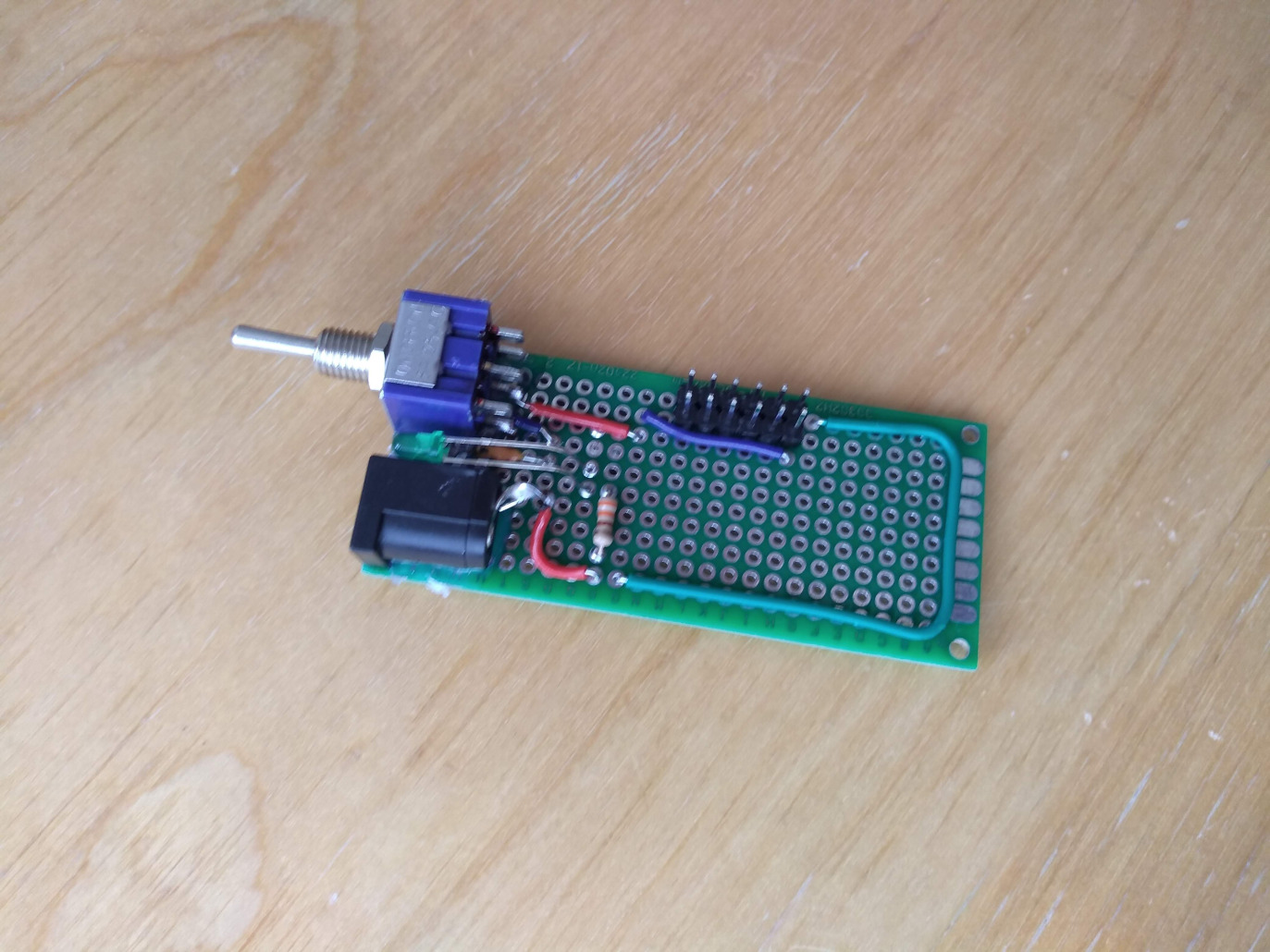
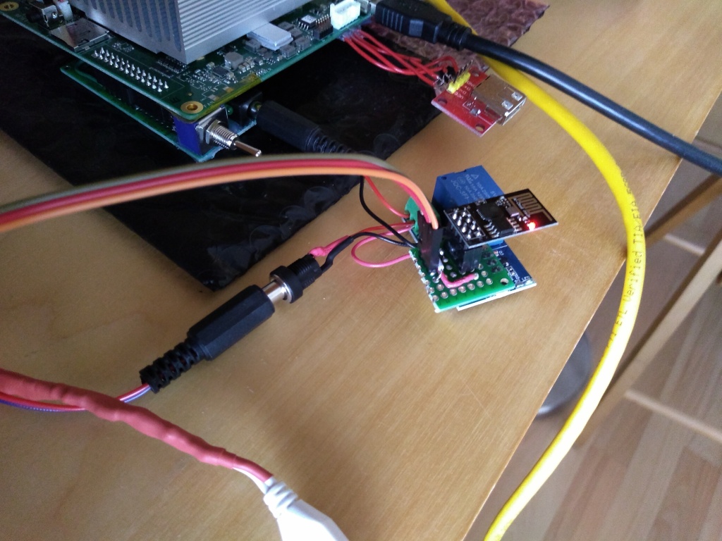
I used a small piece of perfboard, to get access to - and connect - the TX/RX/GND pins of the ESP8266 to the corresponding ones on the AtomicPI (i.e. the CN10 connector):
The ESP01 now plugs in my perfboard - which plugs in the module.
The perfboard from a different angle.
The TX/RX/GND signals from the ESP end up on the CN10 connector of the Atomic PI.
This allowed me to enjoy a remote serial port!
And be able to fully control the booting process and the BIOS:
...which in turn allowed me to perform an OpenBSD installation over this remote serial!
I just needed to type this in the boot menu:
stty com0 115200
set tty com0
Half an hour later, I concluded an installation of a UNIX OS over a remote serial port.
That was a new experience :-)
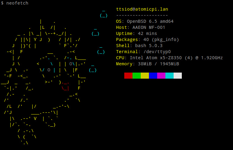
An OS for true Spartans :-)
Overall, this was a very fun and educational process - highly recommended!
And for anyone else that is interested in reproducing this, the code I hacked to run inside the ESP8266 is here.
P.S. Obligatory trolling - who needs Intel's Management Engine? :-)


| Index | CV | Updated: Sun Nov 19 23:06:10 2023 |